Showing posts with label Weft Knitting. Show all posts
Showing posts with label Weft Knitting. Show all posts
30 November 2010
Introduction of Under Lap | Closed Lap | Open Lap
The Under Lap
The underlap shog occurs across the side of the needles remote from the hooks on the front of single-needle
bar, and in the centre of double-needle bar, warp knitting machines. It
supplies the warp yarn between one overlap and the next (Fig.A).The
underlap shog generally ranges from 0 to 3 needle spaces, but it might
be 14 needle spaces or more depending upon the design of the machine and
the fabric structure (although efficiency and production speed will be
correspondingly reduced with long underlaps).
Underlaps as well as
overlaps are essential in warp knitted structures in order to join the
wales of loops together but they may be contributed by different guide
bars.
The Closed Lap
A closed lap is produced when a subsequent underlap shogs in the opposite direction to the preceding overlap, thus lapping the same yarn around the back as well as around the front of the needle (Fig.B).
The Open Lap
An open lap is produced either when a subsequent underlap is in the same direction as the preceding overlap (Fig.C) or an underlap is omitted so that the overlap of the next knitting cycle commences in the needle space where the previous overlap finished. Closed laps are heavier, more compact, more opaque, and less extensible than open laps produced from the same yarn at a comparable knitting quality.
 |
| A.Under lap shog |
The Closed Lap
A closed lap is produced when a subsequent underlap shogs in the opposite direction to the preceding overlap, thus lapping the same yarn around the back as well as around the front of the needle (Fig.B).
 |
| B.Closed Lap |
An open lap is produced either when a subsequent underlap is in the same direction as the preceding overlap (Fig.C) or an underlap is omitted so that the overlap of the next knitting cycle commences in the needle space where the previous overlap finished. Closed laps are heavier, more compact, more opaque, and less extensible than open laps produced from the same yarn at a comparable knitting quality.
15 November 2010
Basic Knitting Elements of a Circular Knitting Machine
NEEDLES
We can divide a needle into three main parts:
A. the hook, which takes and retains the thread tube looped;
B. the hook opening and closing device, that allows the hook to alternatively take a new thread and release the previous one;
C. a system allowing the needle to move and form the loop.
The needles are the most important
stitch forming elements. They are displaced vertically up and down and
are mounted into the tricks or cuts of the knitting cylinder.
There are three types of needles namely:
1. Latch needle
2. Spring bearded needle
There are three types of needles namely:
1. Latch needle
2. Spring bearded needle
3. Compound needle.
We can divide a needle into three main parts:
A. the hook, which takes and retains the thread tube looped;
B. the hook opening and closing device, that allows the hook to alternatively take a new thread and release the previous one;
C. a system allowing the needle to move and form the loop.


22 March 2010
Study on V-bed knitting machine.
Experiment Name: Study on V-bed knitting machine.
Objects:
§ To know about the passage of yarn and fabric of the machine.
§ To know about the different parts and their functions of the machine.
§ To know about the cam arrangement of the machine.
§ To know about the different types of cam and their functions.
Objects:
§ To know about the passage of yarn and fabric of the machine.
§ To know about the different parts and their functions of the machine.
§ To know about the cam arrangement of the machine.
§ To know about the different types of cam and their functions.
Specification:
- Brand: PROTTI
- Feeder no: 4
- Gauge: 8
- Width: 48 inch
- Cam per bed:
- Knit cam- 2 no.s
- Tuck cam- 2 no.s
- Stitch cam- 2no.s
- Yarn package
- Front needle bed
- Yarn guide
- Needle spring
- Tension spring
- Fabric
- Cymbal tension
- Dead weightening system
- Yarn take-up
- Latch needle
- Fabric comb
- Yarn carrier
- Back needle bed
M/c description:
 In
the following figure shows a cross section of a simple hand powered and
manipulated V-bed rib flat machine. The trick walls are replaced at the
needle bed verges by fixed, thinner, polished and specially shaped
knock-over bit edges. In rib gating, a knock-over bit in one bed will be
aligned opposite to a needle trick in the other bed. During knitting,
the edges of the knock-over bits restrain the sinker loops as they pass
between the needles and thus assist in the knocking over of the old
loops and in the formation of the new loops.
In
the following figure shows a cross section of a simple hand powered and
manipulated V-bed rib flat machine. The trick walls are replaced at the
needle bed verges by fixed, thinner, polished and specially shaped
knock-over bit edges. In rib gating, a knock-over bit in one bed will be
aligned opposite to a needle trick in the other bed. During knitting,
the edges of the knock-over bits restrain the sinker loops as they pass
between the needles and thus assist in the knocking over of the old
loops and in the formation of the new loops.The cover plate is a thin metal blade, located in a slot across the top of the needle bed tricks. It prevents the stems of the needles from pivoting upwards out of the tricks as a result of the fabric take down tension drawing the needle hooks downwards whilst allowing the needles to slide freely in their tricks.
Latch opening brushes are attached to the cam plates of both needle beds to ensure that the needle latches are fully opened. The supports of the brushes are adjustable to ensure precise setting of the bristles relative to the needles.
The cam-carriage either slides or runs on ball bearings or wheels, along guide rails, one of which is fixed over the lower end of each needle bed. It is propelled either by hand or from a motor driven continuous roller chain or rubber belt.
Each yarn carrier is attached to a block which slides along a bar, which, like the carriage guide rails, passes across the full width of the machine.
Two levers are usually provided, one at each end of the needle bed. One is for racking the back needle bed, to change the gating of the needle beds for changes of rib set out or rib loop transfer. Cam system of the V-bed hand flat machine:
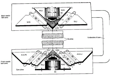
The following figure illustrates the knitting action of a V-bed hand flat machine and the another figure shows the underside of the cam carriage and the cams forming the tracks that guide the needle butts through the knitting system.
The needle butts will enter the traversing cam system from the right during a left to right carriage traverse and from the left during a right to left traverse. For each needle bed there are two raising cams (R), two cardigan cams (C) and two stitch cams (S).
The arrangement as shown in the following figure is referred to as a knitting system. A single system machine will knit one course of rib in one traverse whereas a double system machine will knit two courses of rib per traverse. Sometimes a set of cams in one bed is referred to as a lock.
A (L) – Raising cam (left)
B (R) – Raising cam (right)
C – Tuck cam (left & right)
D (L) – stitch cam (left)
D (R) – stitch cam (right)
E – Guard cam
The knitting action of the V-bed hand flat machine:
The rest position: The tops of the heads of the needles are level with the edge of the knock over bits. The butts of the needles assume a straight line until contacting the raising cams R (R) because the leading stitch cams S and AS (L) are lifted to an inactive position. The lifting action is an alternating action that always lowers the trailing stitch cams and raises the leading stitch cams in each system as the traverse commences. This action prevents needles from being unnecessarily lowered and strain being placed on the old loops prior to the start up of the knitting action.
Clearing:
The
needle butts are lifted as they contact the leading edge of cams R (R),
which raises the needles to ‘tucking in the hook’ height with the
undersurface of cams S (L) acting as guard cams. The needles are lifted
to full clearing height as their butts pass over the top of cardigan
cams C (R) and C (L).
Yarn feeding: The yarn is fed as the needles descend under the control of guard cam (G). The required loop length is drawn by latch needle as it descends the stitch cam S (R).
Knocking over:
Yarn feeding: The yarn is fed as the needles descend under the control of guard cam (G). The required loop length is drawn by latch needle as it descends the stitch cam S (R).
Knocking over:
To
produce synchronized knocking over of both needle beds simultaneously,
the stitch cam S (R) in the front system is set lower than the auxiliary
stitch cam AS (R), so that the latter is rendered ineffective.

Finally
it can be said that the experiment is very important. By this
experiment we may learn how to change the design, how to operate the
machine and how to changing the position of cams to produce different
types of designs which helps us in our practical life.
Subscribe to:
Posts
(Atom)